Tuesday, March 22, 2022

Solved: Omron Microscan WebLink connection failure is caused by avoidable settings

Do NOT set the Omron V430 reader "End Cycle On" to "New Trigger" if its "Trigger mode" is "Continuous".  Set the "End Cycle On" to "Timeout or New Trigger".  

Without the timeout option the CPU does not get a chance to accept the WebLink connection.

Here is a video that show the solution:


https://youtu.be/-Bwe_9T4Ojk


Friday, February 11, 2022

Omron Microscan V430 slow or no connection, a work-around

 I was stumped on why the web page would not come up.  

It goes without saying, check the IP address and subnet mask.

The default IP of the Omron Microscan V430 is   192.168.188.2  subnet mask 255.255.0.0

I could ping it.  I could Telnet into it.  But the webpage wouldn't connect.

Answer: Cover the lens. 

WHAT?  How does covering the lens fix a connection problem?

The camera was in continuous acquisition.  It was spending all of its CPU time on finding and decoding a barcode.  There was no time left to allow connection requests.

Covering up the lens blanks the image.  The barcode search fails immediately, allowing the CPU to perform other tasks.


Thursday, January 13, 2022

Cognex In sight Industrial vision controlled by Labview using Native Mode communication

Hey, just want to document the way I'm using Labview to trigger a Cognex In sight camea.


 Basically, the Cognex In sight is a Telnet server.  The Labview program makes a TPC connection to the camera's IP address on port 21.  The username admin followed by carriage return and line feed is transmitted from Labview.  Then the password, which is blank, so just a carriage return and line feed are sent.  That initialization of the connection is made every time.  While the connection is maintained (open) any of the Native Mode commands can be sent.  See in sight explorer help for a full list of Native Mode commands.   The camera can be triggered by sending SE8\r\n   [note: the \r\n is the escape or slash character representation of Carriage return and line feed respectively.]  The camera will return a number and \r\n that encodes any error in reading or executing the command.  If you get a 1\r\n everything was OK.  After the inspection has completed you need to read out the result.  The native mode command to get a value is GV.  For example, GVc013\r\n will return the value in spreadsheet cell c013.  If you are using  easybuilder you need to create a format string in the "Communication" section.  Get the content of the format string using the command GVJob.Robot.FormatString\r\n

  The video shows how the Labview portion of the code works.  There is a .VI in the form of a functional global variable that encapsulates the communication as a state machine.  It handles the connection, login, command, and closing.  If you want the code let me know in the comments of the video.      


This link is a LabVIEW example.  It is written in LabVIEW 2018

Cognex Native Mode Communication Example https://drive.google.com/file/d/1G3T7LsJA6gZIcHpWeMIAGt_enxl1vMb5/view?usp=sharing


From In-sight explorer help (Links don't work, you need to have in sight explorer):

Basic Native Mode Commands

File & Job Commands

  • Load File: (LF) Loads the specified job from flash memory on the In-Sight vision system, making it the active job.
  • Store File: (TF) Saves the current job in flash memory on the vision system.
  • Read File: (RF) Reads a job from the flash memory on the vision system.
  • Write File: (WF) Sends a job to the flash memory on the vision system.
  • Delete File: (DF) Deletes the specified job or cell data file (.cxd) from flash memory on the vision system.
  • Get File: (GF) Returns the filename of the active job on the vision system.
  • Set Job: (SJ) Loads a job from one of the job slots in flash memory on the vision system, making it the active job.
  • Store Job: (TJ) Saves the current job into the specified slot in flash memory on the vision system.
  • Read Job: (RJ) Reads a job from the specified In-Sight job slot.
  • Write Job: (WJ) Sends a job to the specified job slot in flash memory on the vision system.
  • Delete Job: (DJ) Deletes the job from the specified slot in flash memory on the vision system.
  • Get Job: (GJ) Gets the currently loaded job's ID number.


Image Commands

  • Read BMP: (RB) Sends the current image, in ASCII hexadecimal format, from a vision system to an external device.
  • Read Image: (RI) Sends the current image, in ASCII hexadecimal format, from a vision system to an external device.
  • Write BMP: (WB) Sends image data from an external device to the vision system.
  • Write Image: (WI) Sends image data from an external device to the vision system.


Settings & Cell Value Commands

  • Get Value: (GV) Returns the value in a specified cell or symbolic tag.
  • Set Integer: (SI) Sets an integer value in a specified cell or symbolic tag.
  • Set Float: (SF) Sets a floating point value in a specified cell or symbolic tag.
  • Set Region: (SR) Sets the values of an EditRegion cell or symbolic tag.
  • Set String: (SS) Sets a string value in a specified cell or symbolic tag.
  • Get Info: (GI) Returns system information about the In-Sight vision system.
  • Read Settings: (RS) Reads the system settings data from a vision system.
  • Write Settings: (WS) Sends the system settings data from an external device to the vision system.
  • Store Settings: (TS) Stores the vision system settings to the proc.set file.
  • Set IP Address Lock: (SL) Prevents unauthorized changes to a vision system's IP address.
  • Get IP Address Lock: (GL) Returns the security status of the IP address on a vision system.


Execution & Online Commands

  • Set Online: (SO) Sets the vision system into Online or Offline mode.
  • Get Online: (GO) Returns the Online state of the vision system.
  • Set Event: (SE) Triggers a specified event.
  • Set Event and Wait: (SW) Triggers a specified event and waits until the command is completed to return a response.
  • Reset System: (RT) Resets the vision system (similar to physically power cycling the vision system).
  • Send Message: (SM) Sends a string to the spreadsheet over a Native Mode connection, and optionally, triggers a spreadsheet Event.

Tuesday, January 4, 2022

Gundlach korona (needs lens and mount)


Gundlach korona without a lens or a lens mount.

The original leather handle is still attached.

Back, wet glass plate side.

The glass has etched grid lines.

The camera was used for wind tunnel schlieren photography.

The camera body and both rack and pinion extensions are serial 34.


The bellows are intact and expand freely. 

It needs a lens.  If you have a lead on one please let me know.

Tuesday, September 7, 2021

3D Color space as a cube. RGB HSL and CMYK

Have you ever noticed that color is 3 dimensional?  

We can see Red, Green and Blue.  

What happens if you associate RGB with the 3D world of XYZ?

Replacing the X axis with Red, the Y axis with Green, and the Z axis with Blue creates a rainbow cube.

As a bonus, the color spaces CMYK and HSL (or HSI) are created for FREE!

https://youtu.be/22Fw3QGlIwU

3D Color Cube


The video talks about the inspiration for the 3D color cube, and you can create your own.

Link to the Color cube template PDF:

https://drive.google.com/file/d/1JJMJ_vVwCiQ9uoFJUepSLBFiSZNPPDpY/view?usp=sharing


Friday, September 3, 2021

Best way to visualize 3D depth data

 Depth map images represent the Z (or distance from camera) as brightness or color.

Depth map image created from a laser scan of almonds.

The surfaces are hard for a human to pick out of the image.

In the depth image above there are boxes sitting on the floor.  The image gets brighter the further from the camera.  The distance increases, causing the Z or Depth to have a larger value.  Image displays treat the higher pixel value as a brighter intensity.
  
But you can't tell where the box, or its side walls are.  It is more difficult to tell where the corners and flaps are.


The interesting information for humans (and eventually robots) if to color the image based on the surface, not on the depth.

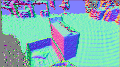
This is the same image from the depth data, but the color is set by the surface normals.  That is, the normal vector to the plane each pixel sits on is encoded as a Red, Green and Blue value.  
 
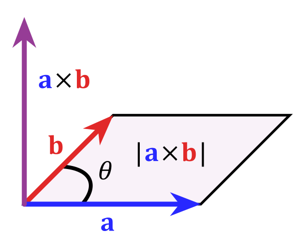
a x b = normal vector (?does that make it an abnormal vector? dumb joke)

The normal vector is found by taking the cross product of two vectors.  The pixel contains an x,y image value and a z from the depth or intensity value.  The two vectors for the cross product are created by subtracting the pixel x,y,z from a neighbor pixel in x axis, and a neighbor pixel in y axis.

The normal vector is 3 dimensional.  There is a convenient way of displaying 3D data by associating the 3D x,y,z to the colors red, green, blue.  This effectively moves the normal vector into the RGB color space.  That is super great because there are many color image machine vision tools!!!
 
But the RGB color space is NOT how humans think about the world!
Artists use a hue, saturation and intensity color space.  The color wheel is a common way for humans to think of red, green and blue.
Color wheel.  Hue revolves around the circumference. Intensity increases toward the center.


  The normal vector traces out a sphere with radius 1.


That is, the normal vector will only touch the surface of a sphere, not the inside of the sphere.  This is great for us.  Converting the normal vector RGB space to HSI or HSL means we can throw away the saturation.  Saturation is the inside of the HSL sphere.


So now look at the color wheel again, but think that you are looking down onto a color sphere

The normal vector pointing out of the image (straight at you) is white.  The normal pointing to the right is red, to the left is cyan, up is violet, down is greenish yellow.

Lets apply this idea to a depth image of a pallet of paper bags.
Depth image, bright pixels are further from camera.

How can you tell the orientation of the stacks of bag bundles on the pallet in the center of the depth image?
Convert the surface normal to an HSL color sphere like this...

From the HSL normal image you can tell where the walls of the bundles are.  You can hopefully see that the bundle in the center is falling off.  It is tilted up and right, giving it a pink or magenta color.
You may even notice that a bundle has fallen onto the ground (The green cyan blob in the image above the pallet.)  It is not noticeable in the depth image.

By coloring the surfaces using a HSL or HSI model, the walls of objects become easy to detect.  For a robot, the orientation or approach angle is part of the color image.

HSI encoded normals image.  White pixels are perpendicular to the camera.  Color (hue) encodes rotation of each surface.


Thanks for reading my blog - Lowell Cady


Thursday, January 21, 2021

Capturing a YUV4:2:2 pixel format image from the USB port, and displaying it as RGB.

 I'm troubleshooting why I can't receive the RGB data stream from the Framos Realsense D435e.  I decided to take a step back to the Intel Realsense D435 USB, and verify the pixel format of the data stream.  


The Realsense software indicates there are multiple RGB camera stream formats:  YUYV, RGB8, RGBA8, etc.


Each of these streams should use a pixel format that is different from the others.  The data in the communication packet should be arranged based on the pixel format.  YUYV is a 16 bit per pixel format that contains the Luminance (brightness) of every pixel, and only half of the Chroma (color) data for each pixel.  The rest of the Chroma data is supplied in the next pixel. So when using YUYV you need to get pixel pairs.  And to make things a little more complicated, you need to convert the YUYV data to RGB data before you get the full color image.  

But the goal of the test was to see what pixel formats can come from the camera.  Turn out, even though there are multiple formats listed, the data in the packet is still only YUYV.   Selecting RGBA8 should require more bytes per pixel, and they should be in a different pixel format, but the data packets all look the same as YUYV. 

I discovered this using Wireshark's USBPcap feature.  The length of the image frame packets did not change when a different stream was selected.


WireShark reports that the image data packet is 115475 bytes long.  I exported the data by right clicking the hex and selecting "Copy as Escaped string", then pasting into notepad.  


The actual image data starts at 0x0113 or 275 bytes into the data packet.

There are 27 bytes of USB packet data, followed by 248 bytes of image header data.  I did not find a way of deciphering this image data header.  I'm sure it's in a standard out there somewhere, but ain't nobody got time for that.  I just calculated the number of bytes that I should get based on 320 x 180 pixels, and 2 bytes per pixel (115200 bytes)  So 115475 - 115200 = 275 should be the start.  And it is!

The YUV format is YUYV 4:2:2  (also this might be called YUY2).

A Microsoft developer doc describes the byte array as:  

Y0U0 Y1V0  Y2U1 Y3V1   ... where there is a Y byte for every pixel, and a 'U' (Chroma blue or Cb) byte for the first (odd) pixels, followed by a 'V' (Chroma red or Cr) byte for the second (even) pixels.

To convert YUV to RGB the YUV4:2:2 is converted to YUV4:4:4 first.  That just means you need Y U and V bytes for every pixel.  If a pixel is missing V, just copy the V from the next even number pixel. If it is missing a U, just copy the U value from the previous pixel. 

Then do some math, maybe with floating point numbers like this:

Make new variables C D & E

C = Y - 16

D = U - 128

E = V - 128

the formulas to convert YUV to RGB is:

R = clip( round( 1.164383 * C                   + 1.596027 * E  ) )

G = clip( round( 1.164383 * C - (0.391762 * D) - (0.812968 * E) ) )

B = clip( round( 1.164383 * C +  2.017232 * D                   ) )

*Clip just means limit the result back to a value from 0 to 255.  You can cast to an unsigned 8bit number to do this.

And here is the result in all it's amazing techno color:


What's up with the green box?  Well just ignore that.  Wire shark only captures 65535 bytes per packet.


Here are the intermediate steps:

Get the Luma Y and Chroma Cb Cr channels for all pixels:

Luma

Chroma Cb


Chroma Cr


Using the algorithm above, convert the pixels to R G B channels.
R


G


B


Wednesday, January 6, 2021

Balluff BVS Serial Command format


Balluff BVS used as a bar code reader

The Balluff BVS-ID-3-005-E is a vision sensor with barcode reader tools.  The sensor can be triggered using an RS-232 serial command.


Balluff BVS001R  BVS-ID-3-005-E  Vision sensor and barcode reader.

I had some trouble figuring out that the serial command and the ethernet command have slightly different syntax.

The RS-232 serial command to trigger the camera is:

TRIGGER<0x00>

  where <0x00> is a byte with the value of zero.

The response is:

<0x02>OK&ACK<0x0D><0x0A>        

  byte value 02 followed by ASCII ending with Carriage Return and Line Feed bytes 13 (0D) and 10 (0A)


When using ethernet the trigger command is:

TRIGGER

No Null byte is needed.

The response is:

OK&ACK<0x00>

The null byte is part of the response.


Why are these different?  I spent about 5 hours troubleshooting this.


Edit 20200121:

And get this, the PLC that needs to send the trigger command can't automatically send the <0x00> null byte at the end of the TRIGGER string.  The PLC's string and serial com library treat the <0x00> as the null termination character for the string.  So it doesn't send the the <0x00> byte.  We tried to concatenate a '$00' in structured text (which is the null byte <0x00>) and it just ignores it.  Ultimately Roger, the programmer of the PLC, had to overwrite the serial communication "Data to Send" register, from 7 to 8 bytes.   Sysmax studio may require the overwrite.


Friday, November 20, 2020

Rotating a point using Quaternions

 The RealSense tracking camera T265 outputs rotation as a quaternion, and translation as a vector.

 This is all the background needed to understand point rotation using quaternions   p' = qpq'

Format of a quaternion q:

The quaternion format displayed is [x,y,z,w], where x,y,z is the vector portion and w is the scalar.

For clarity, lets use this notation to talk about quaternions [qw, qx, qy, qz]. 

Where the realsense quaternion output is just re-ordered and re-labeled.  w is now qw, x is now qx, y is now qy and z is now qz.

qw contains the information about the amount of rotation around the axis contained in qx, qy, qz.

BUT THIS IS IMPORTANT:  

qx, qy, qz is not directly the vector of rotation.

qw = cos( angle of rotation / 2)

qx = sin( angle of rotation / 2)  * the x component of the vector of rotation.

qy = sin( angle of rotation / 2)  * the y component of the vector of rotation.

qz = sin( angle of rotation / 2)  * the z component of the vector of rotation.

Finding Angle of rotation and axis of rotation vector

If you want to find the angle of rotation around the axis vector calculate the arccosine of qw and multiply by 2:

angle of rotation =  2 * (arccos (qw))  

To find the vector that is the axis of rotation qx, qy, and qz must be divided by the sin(angle of rotation/2)

axis vector x component = qx /  sin( angle of rotation / 2)

axis vector y component = qy /  sin( angle of rotation / 2)

axis vector z component = qz /  sin( angle of rotation / 2)


Conjugate quaternion q'

 Rotating the same angle around the opposite vector reverses the rotation.  The vector is simply multiplied by -1.  This is considered the conjugate because the sign of the axis vector components are all reversed.  The conjugate quaternion is needed to flip the quaternion frame of reference when a quaternion is used to rotate a point in space.  The angle of rotation does not change, only the vector is inverted.

To create a conjugate quaternion do the following

qw' = conjugate qw = qw = cos( angle of rotation / 2)

qx' = conjugate qx =  -1 * sin( angle of rotation / 2)  * the x component of the vector of rotation.

qy' = conjugate qy =  -1 * sin( angle of rotation / 2)  * the y component of the vector of rotation.

qz' = conjugate qz =  -1 * sin( angle of rotation / 2)  * the z component of the vector of rotation.


Convert the point to a quaternion  p

 A point can be represented as a vector.  We will use px, py, pz as our point notation.  To create a quaternion from the point just add pw with a value of zero.  But remember that has to be equal to the cosine of the rotation divided by 2.  The arccos(0) = 90 degrees. Multiplied by 2 means the rotation of the point around itself is180 degrees.  [It's confusing I know.  It's all about getting out of a 4D rotation.]

The axis vector of rotation is the point px, py, pz.  That is multiplied by the sine of 180/2.  That ends up being the sine of 90 degrees which equals1.   

point quaternion pw = 0 = cos (180/2) = cos (90) = 0

point quaternion px = px * sin (180/2) = px * sin(90) = px * 1 = px

point quaternion py = py * sin (180/2) = py * sin(90) = py * 1 = py

point quaternion pz = pz * sin (180/2) = pz * sin(90) = pz * 1 = pz


The new point location p'

 To calculate the quaternion rotated location of a point use the formula [NOTE: using quaternion multiplication]

p' = qpq' 

 The order of operation is quaternion p multiplied with q'.  The resulting quaternion m is multiplied by q' to create p'.       m = pq'   and then p' = qm

The values in px', py', and pz' are the rotated x,y,z of the point.

px' = new point location x

py' = new point location y

pz' = new point location z


Quaternion multiplication 

 A quaternion is also written as (qw + qxi + qyj + qzk), where i,j,k represent square root of -1 along 3 complex (imaginary number) axes.  I'm ignoring the 4D complex stuff here because it confused me for a long time.  Lets just look at what happens if you multiply using this format:

(pw + pxi + pyj + pzk) (qw + qxi + qyj + qzk) = 

pw*qw + pw*qxi + pw*qyj + pw*qzk + px*qwi - px*qx + px*qyk - px*qzj + py*qwj - py*qxk - py*qy + py*qzi + pz*qwk + pz*qxj - pz*qyi - pz*qz


= (pw*qw - px*qx - py*qy - pz*qz) + (pw*qx + px*qw + py*qz - pz*qy)i + (pw*qy - px*qz + py*qw + pz*qx)j + (pw*qz + px*qy - py*qx + pz*qw)k

 Multiplication is distributive, and there is a multiplication table for i*j*k = -1 (see blow).

The resulting quaternion product of this multiplication is:  

[Note: I decided to call this quaternion m]

mw = (pw*qw - px*qx - py*qy - pz*qz)

mx = (pw*qx + px*qw + py*qz - pz*qy)

my = (pw*qy - px*qz + py*qw + pz*qx)

mz = (pw*qz + px*qy - py*qx + pz*qw)


i*j*k = -1

The multiplication table for i j k

1 i j k

1 1 i j k

i i −1 k −j

j j −k −1 i

k k j −i −1


https://en.wikipedia.org/wiki/Quaternion


Donate


Thursday, September 17, 2020

Criticism of Marxist literary criticism

 Marxist literary criticism is a way of reading a text in which the reader is to identify the power structures, the oppressed, and the symbols of oppression.  In other words, what is the class struggle occurring in the text.  It is intended to show how capitalism is a social structure that oppresses people.  Through Marxist literary criticism the reader should identify that it is the ruling class that has caused the conflict in which the working class protagonist must struggle.  But what is the end result, logical conclusion, the reader is to arrive at when following Marxist literary criticisms?  

  Marx's answer: You are oppressed and it is someone else's fault.  "They" programmed your brain to oppress you.    

  Marx’s Capital states that "the mode of production of material life determines altogether the social, political, and intellectual life process. It is not the consciousness of men that determines their being, but on the contrary their social being, that determines their consciousness." Put simply, the social situation of the author determines the types of characters that will develop, the political ideas displayed and the economical statements developed in the text. - https://en.wikipedia.org/wiki/Marxist_literary_criticism

  And if only you had 'x' your oppression would end.  [Fill in the variable 'x' with stuff i.e. 'the means of production', 'iPhones, 'Nikes', 'Lancome Mascara'... ]  

There is no self improvement in Marxist literary criticism.  Problems would be solved by just taking the thing you are missing and/or disrupting the social/economic system.  

In short, Marxist criticism is a justification of theft.  

Sometimes we are OK with that justification, like increasing the taxes on Jeff Bezos.  But eventually everyone is in front of the barrel of Marx's critical canon.

Firefighter's Dream sports bar destroyed 

Chicago looting

The consequence, improving yourself makes you a target for someone else to blame.

Wednesday, September 9, 2020

How to turn off hard drive write caching on windows 10 industrial PC's

  Some of our industrial PC's now use Windows 10 Enterprise LTSB or LTSC.  Since the change to windows 10 there has been an increase in file corruptions.  A user.config file gets written at the close of a vision inspection program.  If the PC is shut down with the program running, the operating system will close the program.  Hard drive write caching is active by default.  The operating system thinks that the user.config file has been written to the hard drive, but in reality, the file's data has only been moved to the memory.  It may be clear of the PC's RAM, but it has not been written to the physical platter.  Regardless the operating system turns off the computer's power.  When the PC is turned on again, the partial user.config is read.  Since it is incomplete the program does not reload all of the user settings.  Sometimes the corruption is so bad that the program crashes.

  Write caching is turned off from device manager.  

Open device manager, either by typing Device Manager in the search box:


OR open from "ThisPC" properties in file explorer:


In Device Manager, expand Disk drives.  Right click on the drive. Click Properties in the pop up menu.


In the Policy tab you can uncheck Enable Write Caching:


There is not a significant drop in system benchmak score.  However in practical usage of the PC when ever you switch active programs it takes a noticeable amount of time for the new program window to display.

Benchmark with  write caching on:


Benchmark with write caching off:


The next economic crisis is commercial real estate

 This video talks about why New York city real estate is going unrented for years, and why the rent is never lowered.  The building mortgage is placed into a mortgage back security.  The security is sold to multiple investors.  They now have control of how much rent costs.  Unrented space doesn't lower the value of the building because rent can be added at the end of the mortgage.  If the rent is lowered the mortgage is in default because the building value is lower.  That would require the owner of the building to write a huge check to make up the difference.  Since they can add rent to the end of the mortgage that's what they do, instead of taking the out of pocket loss.  The result is, there could be one space in the building that has rent so high that no one could ever pay it.  It keeps the value of the building high enough to stay out of default. 


https://youtu.be/NdfmMB1E_qk

BUT now with covid-19, offices are empty.  this is going to crush the commercial real estate market.  The commercial mortgage backed securities are going to get hit bad.


https://youtu.be/D7ou4-w2fow 

Thursday, June 11, 2020

My spine was fractured in a head on wreck

On my way to MQ, I was hit head on by a old man driving a buick.  It was 11:00 on monday june 8th.
Reading rd cincinnati, north of Lousantiville.  my spine was fractured.

The non graphic slow motion head on dash cam video
https://youtu.be/EhcXnhqEjOA


The Graphic full speed video of the crash.
https://www.bitchute.com/video/bXECo20NBvCF/

Thursday, April 30, 2020

Thermal / Visible fusion with Omron MEMS temperature sensor and Basler Dart


Omron uses Micro-ElectoMechanical System (MEMS) thermopile to measure temperature at a distance.  The D6T series sensors use the thermoelectric effect (Seebeck effect) in which temperature is converted directly to voltage.  They are sensitive to Longware Infrared (LWIR) at wavelength between 8 and 12 micrometers.


 The sensors are intended to detect human presence in a volume the size of a room.  The optics are fixed, and the angular field of view is wide.  The highest resolution sensor, 32 x 32 pixels has a 90 degree angular field of view.  A reasonable human size field of view (1550 mm x 1550 mm) requires a short working distance of 800 mm.


Omron D6T-32L-01A specs
Price $125
Resolution 32 x 32 pixels (1024 total pixels)
Power supply voltage 4.5 to 5.5 VDC
Current consumption: 19 mA
Accuracy: +- 3 degrees C in the center 16 pixels.
Temperature resolution 0.33 degrees C
Communication format: I2C

Omron example image 32 x 32 pixels.


  To get usable detail in the visible spectrum I would recommend narrowing the angular field of view.  An inexpensive USB camera that is <GenICam> complaint is the Basler dart daA1280-54uc (S-Mount).

Paired with an f4.2 mm focal length s-mount lens (with IR cut filter), the 800 mm working distance gives a 685 x 915 mm field of view.  But the camera needs to be rotated on its side.

The resulting field of view with both the Omron and the Basler sitting next to each other:
Thermal 1572 x 1572 mm @ 49.125 mm/pixel
Visible 685 x 915 mm @ 0.714 mm/pixel


Sunday, April 26, 2020

Ultraviolet light to inactivate COVID-19

Ultraviolet light (UVC) can destroy covid19.  Estimates are 67J/m^2 (6.7mJ/cm^2) will deactivate to 99.9%. 
This video talks about what I've learned on the topic and how I use it to decontaminate the mail.
There are links to research papers showing the "dose" ("fluence") of UVC energey in mJ/cm^2. I show how to convert the units to mWatt seconds / cm^2. And how to calculate the average UVC power output from the typical ebay lamp. Always wear polycarbonate safety glasses around UVC.


Links on the subject I found useful:
2020 COVID-19 Coronavirus Ultraviolet Susceptibility (67J/m^2 see Table 2
https://www.researchgate.net/publication/339887436_2020_COVID-19_Coronavirus_Ultraviolet_Susceptibility

Dose to inactivate multiple pathogens
https://www.ncbi.nlm.nih.gov/pmc/articles/PMC3925713/table/T2/?report=objectonly

Paper "Can biowarfare agents be defeated with light?"
https://www.ncbi.nlm.nih.gov/pmc/articles/PMC3925713/

International ultraviolet association COVID 19 topic
iuva.org/IUVA-Fact-Sheet-on-UV-Disinfection-for-COVID-19
UV - FAQ
http://www.iuva.org/UV-FAQs

The Effects of Mercury Vapour Pressure
http://lamptech.co.uk/Documents/M3%20Spectra.htm

Medium pressure mercury power distribution
https://www.eta-uv.com/en/products/uv-lamps

Testing UV absorption eyewear and sunscreen with a deuterium light source (video)
https://www.youtube.com/watch?v=vwsHRrDYu5o


UV Lamps & UVC Lamp Types
americanairandwater.com/lamps.htm

Ultraviolet Germicidal Irradiation Handbook
https://www.researchgate.net/publication/278717381_Ultraviolet_Germicidal_Irradiation_Handbook

True low pressure ercury lamps are not visible light
"Looking at Mercury Vapour - Periodic Table of Videos"
https://www.youtube.com/watch?v=7ZT7xqwk84E

Tuesday, April 14, 2020

Thermal imaging LWIR differs from CMOS and CCD NIR


There are tutorials online that say you can convert a color camera to an infrared camera.  To be clear, you can remove the IR cut filter and improve the infrared sensitivity of a CCD or CMOS camera.  However, you will not be able to measure temperature in the way that a FLIR thermal camera can.
This is because the thermal cameras detect Long Wave Infrared (LWIR) between 7500 nm and 14000 nm.  Standard video cameras can detect light between 310 nm and 1000 nm (nanometers).


In this chart of a Sony IMX367 color sensor (provided by Matrix-Vision.com), the IR cut filter is indicated in magenta.  Removing the IR-cut filter will allow the R G and B photo-sites (pixels) to absorb energy in the infrared spectrum.
https://www.matrix-vision.com/usb3-vision-camera-with-hi-res-sony-cmos-sensors-mvbluefox3-4.html?camera=BF3-4-0315ZC&col=1&row=pregius

But if the goal is to detect more NIR, just use a monochrome image sensor.  That way the RGB Bayer filter is not limiting any of the pixels.