Saturday, January 26, 2019

Computational lensing or moire lensing as a counteraction to global warming


The technologies are not proven, yet.  However, either computational lensing, or moire lensing could reduce the amount of infrared light that enters the Earth's atmosphere.  A fleet of micro satellites are needed at the Lagrange point L1 between earth and the sun.  They would need to be positioned accurately.  The diffraction around the pattern of satellites would act as a lens to de-focus the IR light.
Possibly placing a filament between satellites could increase the diffraction area, while keeping the weight and complication at a minimum.

Lagrange L1

Moire Lens


https://www.edmundoptics.com/resources/trending-in-optics/moire-lenses/

https://www.sam.math.ethz.ch/~grsam/HS16/MCMP/Photonics%20-%20Introductory%20Lecture.pdf

https://www.photonics.com/Articles/The_Dawn_of_New_Optics_Emerging_Metamaterials/p5/vo170/i1112/a64154

I'll fill this in with details later, just wanted to get the idea out of my head right now.

Friday, January 25, 2019

Rotate a set of 2D circle points around a 3D point so that the +x axis quadrant point crosses through the 3D start point.

Required steps to rotate a set of points around a 3D center and aligned so the x axis quadrant point is the first point in the set.
This was written for a set of points forming a circle.

Input: Center point, X axis alignment point (used to calculate radius, orientation and starting point), number of circular points.

1) Create a translation matrix from the center point.  (4x4 identity with the right most column set to center x, y, z, 1)


2) Calculate the delta between X axis alignment point and center; delta = X_axisAlignmentPoint - centerPoint

3) Use delta to calculate the radius of the circle. radius = sqrt( delta.x*delta.x + delta.y*delta.y + delta.z* delta.z)

4) The x axis quadrant of the circle is a point at radius,0,0.  circleXQuad = (radius,0,0)  [note: The x value = radius]

5) Create an array of points on a circle, centered at 0,0,0 with a radius from step 3, on the x,y plane.

6) Add the first point of the array to the end of the array to close the circle

7) Find the rotation needed around Z axis in order to put "delta" on the XZ plane [ eliminate the Y value (y = 0)].  Get the angle using arcTan2 of delta.  rotation around Z =  tan^-1(delta.y / delta.x)  [note: arcTan2 should maintain the sign of the angle]

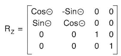
8) Create a Z axis rotation matrix from the angle found in step 7.  Lets call it Rz.

9) Translate delta using the Z axis rotation matrix, Rz.  This will create a new point, delta' [delta prime], where the point is radius distance from 0,0,0, but y is zero (delta'.y = 0).
delta' = [Rz][delta]

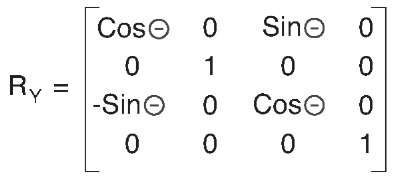
10) Find the rotation needed around the Y axis to put delta' on the X axis.  This will make delta'.z = 0.  The angle may need to be negative.  Rotation around Y = tan^-1(delta'.z/ delta'.x)

11) Build a rotation matrix for Y rotation.

12) The rotation matrices will put the X axis alignment point at the circle's x axis quadrant.  The inverse of this is needed to put the circle's x axis quadrant point at the the input X axis alignment point.  Create the inverse rotation matrices, Ry^-1 and Rz^-1.  The Circle points will be transformed 1st by the inverse Y rotation (Ry^-1), and then by the inverse Z rotation (Rz^-1). 
Edit 20190905: Multiply the Rz and Ry matricies, then get the inverse of the result.
([Rz][Ry])^-1 
  (If you get the inverse Rz and Ry first (as I suggested before 20190905), then you need to reverse the order they are multiplied  it would be [Ry^-1][Rz^-1]. )
The circle will be rotated to the correct orientation, matching the orientation of the original delta point, but centered at 0,0,0.

13) Move the circle to the input center point using the translation matrix from step 1.  Multiply all of the oriented circle points by the translation matrix.  The circle will be centered on the input center point.

Wednesday, January 16, 2019

An idea to normalize camera sensitivity measurements, new unit us*lux

Image sensors are linear photon measuring devices.  Their output signals are are at a linear scale to the photon energy they receive.  [Unlike how humans perceive light with a gamma curve.]

I'm working with a stock Microscan Microhawk MV-40 (running the ID firmware), and need to lower the exposure time.  The built in light is giving me 600 lux at the location of the bar code.  This results in an exposure time of 4150 microseconds (us).  If I increase the light, more lux, the exposure will decrease, less microseconds.  Ignoring the sensor gain, there should be an inverse linear relation between lux and exposure time.  So that got me thinking...

Is exposure time multiplied by lux a constant for a camera?
Can I use a new unit, us*lux to create a constant?

I think the answer is yex, er, yes sort of, almost, very close to yes with the tools I have.

The built in LED yields ~600 lux at 190 mm.  The camera set it's exposure to 4150 us.
4150 us * 600 lux = 2,490,000 us*lux


Adding a white smart vision L300, I can get to 3000 lux.  The camera decided to use an exposure of 850 us.


850 us * 3000 lux = 2,550,000 us*lux


So under either light sources the microsecond * lux values are about 2,500,000, or 2.5 million us*lux.

I should be able to get an exposure of 50 us if I have 50,000 lux...
us = 2,500,000 us*lux / 50,000 = 50 us

This is more useful the other way around...
If I know that I MUST have an exposure not more than 50 us, how much light is needed?
lux = 2,500,000 us*lux  / 50 us = 50,000 lux.

Look, don't get too wrapped up in the details here.

Problem 1 is Lux is a measurement of light striking a surface, not light emitted by a light source.
Problem 2 is that I am ignoring the effect of the sensor's gain setting.  Increasing the gain will act as a multiplier to the us*lux value
Problem 3 maybe the unit should be lux*us instead of us*lux.  That's not really a problem, it's just a preference.  You decide.

I just like the unit us*lux as a short hand for how much light I'm going to need when a vision system gets designed.


Thursday, January 3, 2019

On Windows 10 network traffic slowing down UI events

  Quick note (mostly to myself), when using a GigE camera make sure to enable software triggering.  I found out Labview's "IMAQdx Configure Grab" will stream images in the background even if the frames are not being used.  The network gets swamped with data, useless data, between the camera and the PC, at 1 billion bits per second.  Every time the camera has an image ready it sends it to the computer.  The computer swaps out the last image with the new one, but just keep it in memory.  It doesn't get displayed or even copied out of memory unless the "Grab image" is called.  To alleviate the bandwidth flood, set the camera trigger mode ON, and set the trigger source to Software Trigger.
This way the camera won't get an image until it is asked to get an image.  The IMAQdx property node is used to activate the software trigger.  The property node's "ActiveAttribute" must be set to "TriggerSoftware".  The property node's "ValueBool" is set to "True".  Follow this up with a "Grab" to get the image.  This way the network is only used when you want an image.

LabView Configure Grab and TriggerSoftware properrty node.  

  When the network card was flooded, Windows 10 was slow to respond to mouse clicks.  Some other HID functions, like key presses, would take over 20 seconds to be processed.  I guess that the network traffic had a higher event priority than the user interface events.  However, mouse movements always worked, clicks did not.  The problem vanished once the network traffic was squelched.