Tuesday, September 7, 2021

3D Color space as a cube. RGB HSL and CMYK

Have you ever noticed that color is 3 dimensional?  

We can see Red, Green and Blue.  

What happens if you associate RGB with the 3D world of XYZ?

Replacing the X axis with Red, the Y axis with Green, and the Z axis with Blue creates a rainbow cube.

As a bonus, the color spaces CMYK and HSL (or HSI) are created for FREE!

https://youtu.be/22Fw3QGlIwU

3D Color Cube


The video talks about the inspiration for the 3D color cube, and you can create your own.

Link to the Color cube template PDF:

https://drive.google.com/file/d/1JJMJ_vVwCiQ9uoFJUepSLBFiSZNPPDpY/view?usp=sharing


Friday, September 3, 2021

Best way to visualize 3D depth data

 Depth map images represent the Z (or distance from camera) as brightness or color.

Depth map image created from a laser scan of almonds.

The surfaces are hard for a human to pick out of the image.

In the depth image above there are boxes sitting on the floor.  The image gets brighter the further from the camera.  The distance increases, causing the Z or Depth to have a larger value.  Image displays treat the higher pixel value as a brighter intensity.
  
But you can't tell where the box, or its side walls are.  It is more difficult to tell where the corners and flaps are.


The interesting information for humans (and eventually robots) if to color the image based on the surface, not on the depth.

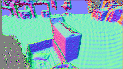
This is the same image from the depth data, but the color is set by the surface normals.  That is, the normal vector to the plane each pixel sits on is encoded as a Red, Green and Blue value.  
 
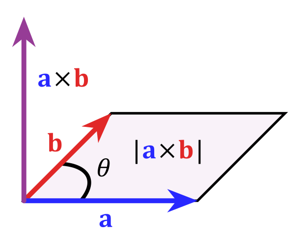
a x b = normal vector (?does that make it an abnormal vector? dumb joke)

The normal vector is found by taking the cross product of two vectors.  The pixel contains an x,y image value and a z from the depth or intensity value.  The two vectors for the cross product are created by subtracting the pixel x,y,z from a neighbor pixel in x axis, and a neighbor pixel in y axis.

The normal vector is 3 dimensional.  There is a convenient way of displaying 3D data by associating the 3D x,y,z to the colors red, green, blue.  This effectively moves the normal vector into the RGB color space.  That is super great because there are many color image machine vision tools!!!
 
But the RGB color space is NOT how humans think about the world!
Artists use a hue, saturation and intensity color space.  The color wheel is a common way for humans to think of red, green and blue.
Color wheel.  Hue revolves around the circumference. Intensity increases toward the center.


  The normal vector traces out a sphere with radius 1.


That is, the normal vector will only touch the surface of a sphere, not the inside of the sphere.  This is great for us.  Converting the normal vector RGB space to HSI or HSL means we can throw away the saturation.  Saturation is the inside of the HSL sphere.


So now look at the color wheel again, but think that you are looking down onto a color sphere

The normal vector pointing out of the image (straight at you) is white.  The normal pointing to the right is red, to the left is cyan, up is violet, down is greenish yellow.

Lets apply this idea to a depth image of a pallet of paper bags.
Depth image, bright pixels are further from camera.

How can you tell the orientation of the stacks of bag bundles on the pallet in the center of the depth image?
Convert the surface normal to an HSL color sphere like this...

From the HSL normal image you can tell where the walls of the bundles are.  You can hopefully see that the bundle in the center is falling off.  It is tilted up and right, giving it a pink or magenta color.
You may even notice that a bundle has fallen onto the ground (The green cyan blob in the image above the pallet.)  It is not noticeable in the depth image.

By coloring the surfaces using a HSL or HSI model, the walls of objects become easy to detect.  For a robot, the orientation or approach angle is part of the color image.

HSI encoded normals image.  White pixels are perpendicular to the camera.  Color (hue) encodes rotation of each surface.


Thanks for reading my blog - Lowell Cady


Thursday, January 21, 2021

Capturing a YUV4:2:2 pixel format image from the USB port, and displaying it as RGB.

 I'm troubleshooting why I can't receive the RGB data stream from the Framos Realsense D435e.  I decided to take a step back to the Intel Realsense D435 USB, and verify the pixel format of the data stream.  


The Realsense software indicates there are multiple RGB camera stream formats:  YUYV, RGB8, RGBA8, etc.


Each of these streams should use a pixel format that is different from the others.  The data in the communication packet should be arranged based on the pixel format.  YUYV is a 16 bit per pixel format that contains the Luminance (brightness) of every pixel, and only half of the Chroma (color) data for each pixel.  The rest of the Chroma data is supplied in the next pixel. So when using YUYV you need to get pixel pairs.  And to make things a little more complicated, you need to convert the YUYV data to RGB data before you get the full color image.  

But the goal of the test was to see what pixel formats can come from the camera.  Turn out, even though there are multiple formats listed, the data in the packet is still only YUYV.   Selecting RGBA8 should require more bytes per pixel, and they should be in a different pixel format, but the data packets all look the same as YUYV. 

I discovered this using Wireshark's USBPcap feature.  The length of the image frame packets did not change when a different stream was selected.


WireShark reports that the image data packet is 115475 bytes long.  I exported the data by right clicking the hex and selecting "Copy as Escaped string", then pasting into notepad.  


The actual image data starts at 0x0113 or 275 bytes into the data packet.

There are 27 bytes of USB packet data, followed by 248 bytes of image header data.  I did not find a way of deciphering this image data header.  I'm sure it's in a standard out there somewhere, but ain't nobody got time for that.  I just calculated the number of bytes that I should get based on 320 x 180 pixels, and 2 bytes per pixel (115200 bytes)  So 115475 - 115200 = 275 should be the start.  And it is!

The YUV format is YUYV 4:2:2  (also this might be called YUY2).

A Microsoft developer doc describes the byte array as:  

Y0U0 Y1V0  Y2U1 Y3V1   ... where there is a Y byte for every pixel, and a 'U' (Chroma blue or Cb) byte for the first (odd) pixels, followed by a 'V' (Chroma red or Cr) byte for the second (even) pixels.

To convert YUV to RGB the YUV4:2:2 is converted to YUV4:4:4 first.  That just means you need Y U and V bytes for every pixel.  If a pixel is missing V, just copy the V from the next even number pixel. If it is missing a U, just copy the U value from the previous pixel. 

Then do some math, maybe with floating point numbers like this:

Make new variables C D & E

C = Y - 16

D = U - 128

E = V - 128

the formulas to convert YUV to RGB is:

R = clip( round( 1.164383 * C                   + 1.596027 * E  ) )

G = clip( round( 1.164383 * C - (0.391762 * D) - (0.812968 * E) ) )

B = clip( round( 1.164383 * C +  2.017232 * D                   ) )

*Clip just means limit the result back to a value from 0 to 255.  You can cast to an unsigned 8bit number to do this.

And here is the result in all it's amazing techno color:


What's up with the green box?  Well just ignore that.  Wire shark only captures 65535 bytes per packet.


Here are the intermediate steps:

Get the Luma Y and Chroma Cb Cr channels for all pixels:

Luma

Chroma Cb


Chroma Cr


Using the algorithm above, convert the pixels to R G B channels.
R


G


B


Wednesday, January 6, 2021

Balluff BVS Serial Command format


Balluff BVS used as a bar code reader

The Balluff BVS-ID-3-005-E is a vision sensor with barcode reader tools.  The sensor can be triggered using an RS-232 serial command.


Balluff BVS001R  BVS-ID-3-005-E  Vision sensor and barcode reader.

I had some trouble figuring out that the serial command and the ethernet command have slightly different syntax.

The RS-232 serial command to trigger the camera is:

TRIGGER<0x00>

  where <0x00> is a byte with the value of zero.

The response is:

<0x02>OK&ACK<0x0D><0x0A>        

  byte value 02 followed by ASCII ending with Carriage Return and Line Feed bytes 13 (0D) and 10 (0A)


When using ethernet the trigger command is:

TRIGGER

No Null byte is needed.

The response is:

OK&ACK<0x00>

The null byte is part of the response.


Why are these different?  I spent about 5 hours troubleshooting this.


Edit 20200121:

And get this, the PLC that needs to send the trigger command can't automatically send the <0x00> null byte at the end of the TRIGGER string.  The PLC's string and serial com library treat the <0x00> as the null termination character for the string.  So it doesn't send the the <0x00> byte.  We tried to concatenate a '$00' in structured text (which is the null byte <0x00>) and it just ignores it.  Ultimately Roger, the programmer of the PLC, had to overwrite the serial communication "Data to Send" register, from 7 to 8 bytes.   Sysmax studio may require the overwrite.