Sunday, September 29, 2019

Windows drive activity LED using NeoPixels


So my coworker Charlie had a million dollar idea;

Charlie - "What if there was a light that would turn on when your drives are accessed?!"
me - "Like on a floppy, or a CD drive, or the HDD LED on a tower case? 'cause those exist."
Charlie - "Yeah, but what if you have more than one hard drive?  You can't tell which drive is being accessed."
me - ..... [speechless because this never occurred to me.]

Charlie went on to describe a youtube video by Barnacules Nerdgasm in which he mines the WBEMTest for disk BytesPerSec.  Barnacules even writes a task tray program that blinks an icon when there is drive activity.

So anyway, the Barnacules source code is available;
Download HDDLED Source Code @ http://bit.ly/hddledsource

But it still has a single indicator for multiple drives.
This is where the NeoPixel comes in.  It is an addressable RGB LED from Adafruit.  https://www.adafruit.com/product/1463

By editing the Barnacules code each LED can flash in sync with each drive.  My edit of his code is linked below.

Still one more missing piece, an Arduino to control the NeoPixels.  While Adafruit has some good options (like the feather and the itsy bitsy https://www.adafruit.com/product/3677), I have some even smaller 32u4 based arduino clones.
 On ebay search for 32u4 beetle. 
This little gut just plugs right into a usb port.  There are 3 connections from the beetle to the neopixels, 5V to 5V, Gnd to Gnd, and beetle A2 connects to the neopixel Data In.

Right click on the icon to open the window.  Select the com port of the Beetle. close the window to make it go back to the tray.


The arduino IDE serial monitor (115200) can be used to control the LEDs directly.
I created a simple protocol that will change the RGB values, save the current setting to the eeprom, and load a setting from the eeprom.

type ? and hit enter to get the command list.

Bonus fact:
The 16 LED neopixel ring fits perfectly inside of a 25.5 to 46 mm step up filter adapter.  I use this combination as a cheap RGB ring light for Fujinon and Edmund Optics c mount lenses.

Links:
Link to the video tutorial that creates the hard drive monitor windows task bar program:
https://youtu.be/NO_gqbE3e54

Link to the windows DiskInUse.exe program (the tray icon program).  [You need to download all 5 files]:
https://drive.google.com/drive/folders/1D6-6OxUc0U8kgMIwfBFOwcCH4KyNw9Rm

Link to the Arduino NeoPixel program for the beetle:
https://drive.google.com/drive/folders/1rrfyhyyoC2KdOJnyA5NroIgqLb55Yq_m

Make sure you load the adafruit neopixel library in the arduino IDE.

This is the full project file that includes my edits of Barnecules' code:
https://drive.google.com/drive/folders/13CgYQedi1gVSaGxQgzgVjCNX0y1hNcYT


The following screen captures are just here to help me remember the location of the data.  You don't need to access this, but it is amazing how much can be accessed from the OS.
click Connect when it opens.

when connected click enum Classes
select Recursive then OK
win32_PerfFormattedData_PerfDisk_PhysicalDisk
DiskBytesPersec

Thursday, August 22, 2019

Google Vision API and Labview


Two years ago I used Google Vision API with Labview.  I've forgotten some of the details, so I'm making this post to record what I remember.

First, the Vision API and documentation, and examples are found here https://cloud.google.com/vision/
[There are not Labview examples]

This is a good starting point  https://cloud.google.com/vision/docs/how-to

The Vision API is a cloud service, so you need to create an account.

In Google Cloud Platform you must enable Vision API.

The Vision API will bill you if you go over 1000 images, so you need a payment method. [But there is a free trial that will last for a few months.]

The Vision API uses a key to validate your HTTP request.

The HTTP request will point to an image URL, so your images need to be accessible from the web.  Google has cloud storage 'buckets' that your images can be uploaded to.  The HTTP request will point to the image URL in the bucket.

Labview has an HTTP client pallet:

Open a Handle.
Add a header Content-Type  Application/json
Add a second header  Accept-Encoding    Application/json

Build the body of the request and POST to the Vision URL. 
The body of the response will need to be converted from json.
Finally, close the HTTP request.

---
To parse the json string you need to create a type def that matches the format of the json data.

The type def is made from an array of type "response"
Type "responce" is 2 1D arrays of type "labelAnnotation" and "logoAnnotation"
Type "labelAnnotation" is a cluster of Type string with the label "mid", Type string labeled "description", and Type single labeled "score"
Type "logoAnnotation" is a cluster of Type string with the label "mid", Type string labled "Description" and Type single labeled "score"

I recall that the organization of the TypeDef must match the JSON order, or there will be an error when "Unflatten from JSON" is used.


What you do with the data after that is up to you...  I just overlaid the text onto the image.

Here is a screen shot for the whole VI


Youtube results
https://youtu.be/VlVWLpdqbjc


Monday, July 8, 2019

Texturing the Intel Real Sense point cloud in Labview with the color camera


Intel has supplied a great LabView wrapper for the RealSense SDK 2.0 (LibRealSense DLL).
LabView Wrapper     (https://github.com/IntelRealSense/librealsense/tree/development/wrappers/labview)


However, as of 20190708  [July 8 2019] the wrapper uses SDK 2.11.0, which does not support the T265 tracking camera.  Also, the color camera of the D435 doesn't use the wrapped SDK.

This post will outline the process of using the D435 color camera to texture the point cloud.

Point cloud displayed with color texture


- To get images from the color camera in labview, you need to use National Instruments Vision Acquisition software.  In labview this is the NI-IMAQdx pallete.
- To manipulate the images you need the NI Vision Development Module.  It contains most of the sub VI's I use to turn the color image into a point cloud texture.


- Open the color camera and configure a Grab where you are initializing the Intel RealSense camera.
- Create an image type to be used later by the Grab vi.  I do this in a Functional Global Variable.
The Functional Global Variable holds all the images, and uses the serial number of the camera to create image names.


I use a sequence to acquire the image and depth data.  First I get the data from the RealSense SDK, then I get the color image from the NI-IMAQdx Grab vi.  Note that the Grab VI takes the image in memory, it doesn't wait for the next image.

All the wrapped DLL VIs that get depth and left grayscale imge data.


The ni-imaqdx grab is in the lower left.  It just needs to camera session from the initialization, and an image type [pointer].

The depth information is created based on the left grayscale camera.


! ! ! The Color camera and the Left grayscale camera do NOT have the same Field Of View (FOV).
!  !  !  ! And they are not the same size.
!   !   !   !   ! And the color camera, even though it has a higher resolution, has a smaller FOV


- 4 points are needed to define a Tetragon.  The points need to be where the greyscale image's corners would be in the color image,  You can calculate that from the scale difference betweeen the images, but I do it by calculating a homography matrix between cooresponding points in the two images, then multiplying the grayscale corner points by the homography matrix.

- Place 4 small object in the corners of the color image.
- Use an ROI tool to identify the corresponding points in the color and the left grayscale image.


- Solve the Homography matrix from the corresponding points


- Translate the grayscale corner points to the color image (even though we know they are outside of the color image.)

- Using the NI Tetragon Extract VI, pass in the translated grayscale corners and the dimensions of the grayscale mage, as well as the color image and a destination image.

- The output of the extract will be the color image scaled and shifted to line up with the grayscale and the depth image.
!! NOTE: The tetragon extract does not perform perspective correction.  The 4 points need to be on the same plane.  Please leave a comment if you have a better solution for labview.

- The .XYZ point cloud needs an RGB value from each pixel in the depth image.  In this step of the sequence the XYZ, RGB, and Normals are calculated.  More detail about the XYZ and RGB arrays will follow.

- The XYZ array converts each depth pixel to it's X,Y,Z location with Z being a measure of distance from the camera.  The X, and Y are scaled based on the Z  distance and the camera focal length.  The Intel realSense camera provides the intrinsic camera model where focal length is in pixels.

[Edit 20210220 - 
Zworld = the value of the depth pixel in millimeters 
Xworld =  ( (xdepth - ppx) * Zworld) / fx
Yworld = ( ( ydepth - ppy) * Zworld) / fy

where 
xdepth is the x value of the pixel in the depth image where top left = 0 and bottom right = image width -1
ydepth is the y value of the pixel in the depth image where top left = 0 and bottom right = image height -1
ppx is the principal point in x.  this is often the center of the image.
ppy is the principal point in y, again often the center y of the image.
fx is the focal length of the lens but its units are in pixels, not in millimeters.  
fy is the focal length of the lens in pixels, and is pretty much the same as fx.
Note, that the value of the pixel in the depth image  is the distance in millimeters that object is from the camera.  

To find the camera intrinsic parameters run the 
rs-sensor-control.exe
that will is part of the RealSense SDK
C:\Program Files (x86)\Intel RealSense SDK 2.0\tools

For a 1280x720 depth image from the D435 you can these values (which are close, but wont match your camera perfectly)
fx 645.912
fy 645.912
ppx 640
ppy 360

For a 640 x 360 depth image you can use these intrinsics (again, not exact)
fx 322.956
fy 322.956
ppx 320
ppy 180

Notice that the scale of the 640x320 is 1/2 of the 1280 x720. 
  end Edit ]

- The texture image must be converted to a 1D array of RGB values to match the XYZ array.

- Although outside of the scope of this post, this is how I calculate the normals per point:
The 2D depth array is used in this loop.

- The 1D arrays are placed into a point cloud functional global variable.

- The Point Cloud FGV has a write .XYZ text file function.  Once written the text file can be read by other programs, such as CloudCompare (https://www.danielgm.net/cc/)  and MeshLab.


-----
 Here is a sample point cloud:
Miscellaneous stuff

https://drive.google.com/file/d/1BqyCqsdOnIXcrCtNC4F2uBuuFD8Wcr-S/view?usp=sharing


If you open it in cloud compare, make sure to set the column to X, Y, Z, Normal X, Normal Y, Normal Z, Color.R(0-1), Color G(0-1), Color B(0-1), Ignore the last column.


Example viewed in cloud compare:


Wednesday, March 13, 2019

Intel Realsense Tracking camera automatically transforms Depth camera data.


The Intel Realsense technology is an inexpensive human scale visual distance (depth) measurement system.  The recent tracking camera isn't just an addition to the line, it is multiplier.  The tracking camera knows where it is pointed, and where it is in space.  The translation and rotation data will transform the depth data automatically in the Realsense Viewer.   It does this in real-time, at about 30 fps.  Combined these devices could be used to create an area scanner.  The point clouds created from sampled frames will be close to correct orientation. 

Video of the two cameras working together:
Intel Realsense Tracking and Depth, T265 with a D435

https://youtu.be/z4O1t30OrlQ

Wednesday, March 6, 2019

Monday, March 4, 2019

Microscan Microhawk Telnet Help command

If you log into the Microscan MicroHawk via Telnet [Login: target  password:password]
Enter the Help command at the -> prompt.
A list of commands will be displayed.
-> help


Additional Help commands such as netHelp will display even more commands.
-> netHelp


Saturday, January 26, 2019

Computational lensing or moire lensing as a counteraction to global warming


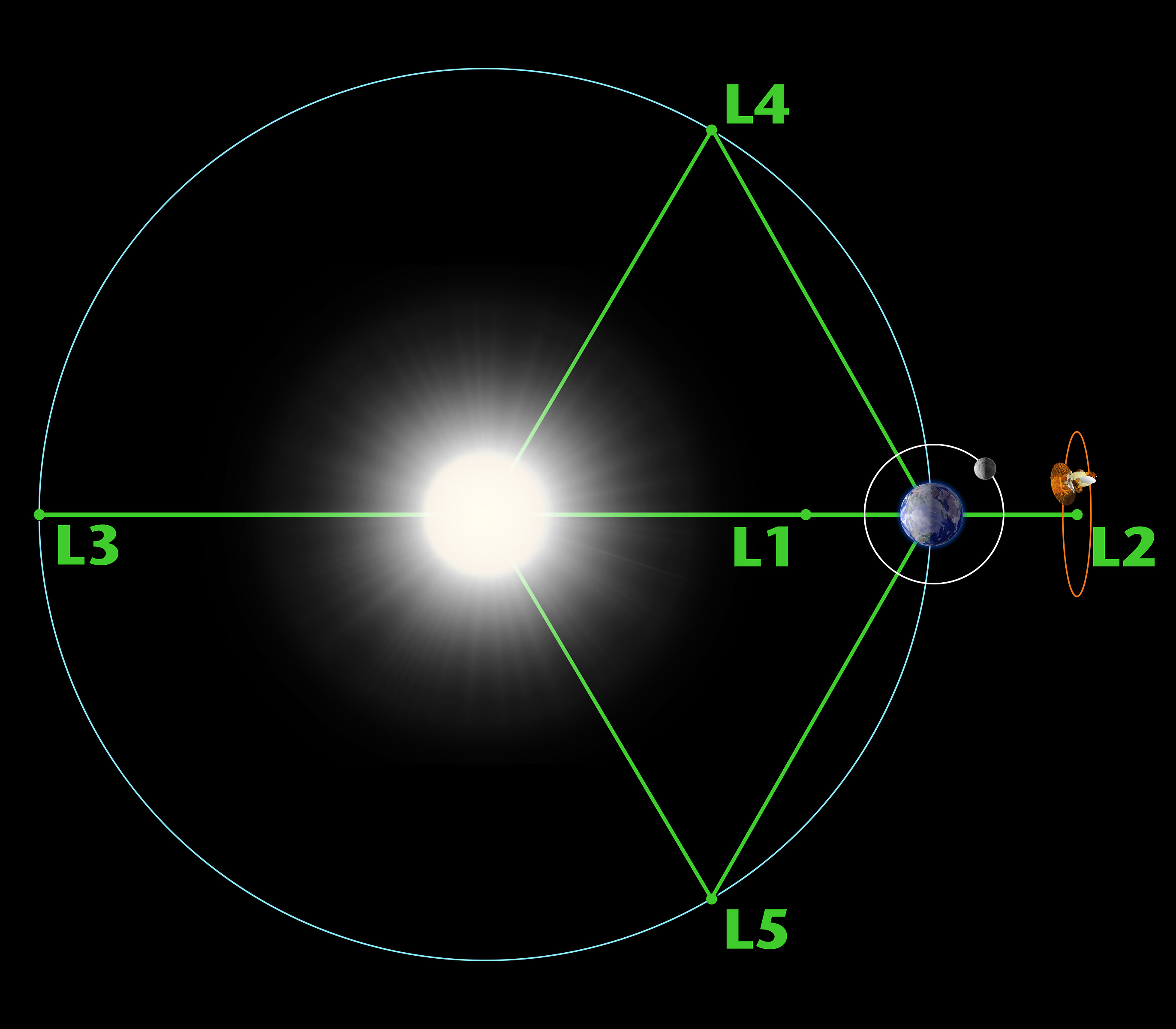
The technologies are not proven, yet.  However, either computational lensing, or moire lensing could reduce the amount of infrared light that enters the Earth's atmosphere.  A fleet of micro satellites are needed at the Lagrange point L1 between earth and the sun.  They would need to be positioned accurately.  The diffraction around the pattern of satellites would act as a lens to de-focus the IR light.
Possibly placing a filament between satellites could increase the diffraction area, while keeping the weight and complication at a minimum.

Lagrange L1

Moire Lens


https://www.edmundoptics.com/resources/trending-in-optics/moire-lenses/

https://www.sam.math.ethz.ch/~grsam/HS16/MCMP/Photonics%20-%20Introductory%20Lecture.pdf

https://www.photonics.com/Articles/The_Dawn_of_New_Optics_Emerging_Metamaterials/p5/vo170/i1112/a64154

I'll fill this in with details later, just wanted to get the idea out of my head right now.

Friday, January 25, 2019

Rotate a set of 2D circle points around a 3D point so that the +x axis quadrant point crosses through the 3D start point.

Required steps to rotate a set of points around a 3D center and aligned so the x axis quadrant point is the first point in the set.
This was written for a set of points forming a circle.

Input: Center point, X axis alignment point (used to calculate radius, orientation and starting point), number of circular points.

1) Create a translation matrix from the center point.  (4x4 identity with the right most column set to center x, y, z, 1)


2) Calculate the delta between X axis alignment point and center; delta = X_axisAlignmentPoint - centerPoint

3) Use delta to calculate the radius of the circle. radius = sqrt( delta.x*delta.x + delta.y*delta.y + delta.z* delta.z)

4) The x axis quadrant of the circle is a point at radius,0,0.  circleXQuad = (radius,0,0)  [note: The x value = radius]

5) Create an array of points on a circle, centered at 0,0,0 with a radius from step 3, on the x,y plane.

6) Add the first point of the array to the end of the array to close the circle

7) Find the rotation needed around Z axis in order to put "delta" on the XZ plane [ eliminate the Y value (y = 0)].  Get the angle using arcTan2 of delta.  rotation around Z =  tan^-1(delta.y / delta.x)  [note: arcTan2 should maintain the sign of the angle]

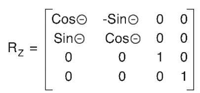
8) Create a Z axis rotation matrix from the angle found in step 7.  Lets call it Rz.

9) Translate delta using the Z axis rotation matrix, Rz.  This will create a new point, delta' [delta prime], where the point is radius distance from 0,0,0, but y is zero (delta'.y = 0).
delta' = [Rz][delta]

10) Find the rotation needed around the Y axis to put delta' on the X axis.  This will make delta'.z = 0.  The angle may need to be negative.  Rotation around Y = tan^-1(delta'.z/ delta'.x)

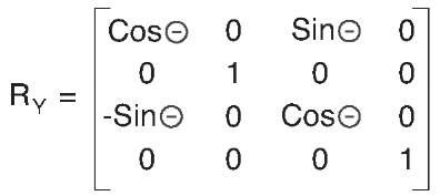
11) Build a rotation matrix for Y rotation.

12) The rotation matrices will put the X axis alignment point at the circle's x axis quadrant.  The inverse of this is needed to put the circle's x axis quadrant point at the the input X axis alignment point.  Create the inverse rotation matrices, Ry^-1 and Rz^-1.  The Circle points will be transformed 1st by the inverse Y rotation (Ry^-1), and then by the inverse Z rotation (Rz^-1). 
Edit 20190905: Multiply the Rz and Ry matricies, then get the inverse of the result.
([Rz][Ry])^-1 
  (If you get the inverse Rz and Ry first (as I suggested before 20190905), then you need to reverse the order they are multiplied  it would be [Ry^-1][Rz^-1]. )
The circle will be rotated to the correct orientation, matching the orientation of the original delta point, but centered at 0,0,0.

13) Move the circle to the input center point using the translation matrix from step 1.  Multiply all of the oriented circle points by the translation matrix.  The circle will be centered on the input center point.

Wednesday, January 16, 2019

An idea to normalize camera sensitivity measurements, new unit us*lux

Image sensors are linear photon measuring devices.  Their output signals are are at a linear scale to the photon energy they receive.  [Unlike how humans perceive light with a gamma curve.]

I'm working with a stock Microscan Microhawk MV-40 (running the ID firmware), and need to lower the exposure time.  The built in light is giving me 600 lux at the location of the bar code.  This results in an exposure time of 4150 microseconds (us).  If I increase the light, more lux, the exposure will decrease, less microseconds.  Ignoring the sensor gain, there should be an inverse linear relation between lux and exposure time.  So that got me thinking...

Is exposure time multiplied by lux a constant for a camera?
Can I use a new unit, us*lux to create a constant?

I think the answer is yex, er, yes sort of, almost, very close to yes with the tools I have.

The built in LED yields ~600 lux at 190 mm.  The camera set it's exposure to 4150 us.
4150 us * 600 lux = 2,490,000 us*lux


Adding a white smart vision L300, I can get to 3000 lux.  The camera decided to use an exposure of 850 us.


850 us * 3000 lux = 2,550,000 us*lux


So under either light sources the microsecond * lux values are about 2,500,000, or 2.5 million us*lux.

I should be able to get an exposure of 50 us if I have 50,000 lux...
us = 2,500,000 us*lux / 50,000 = 50 us

This is more useful the other way around...
If I know that I MUST have an exposure not more than 50 us, how much light is needed?
lux = 2,500,000 us*lux  / 50 us = 50,000 lux.

Look, don't get too wrapped up in the details here.

Problem 1 is Lux is a measurement of light striking a surface, not light emitted by a light source.
Problem 2 is that I am ignoring the effect of the sensor's gain setting.  Increasing the gain will act as a multiplier to the us*lux value
Problem 3 maybe the unit should be lux*us instead of us*lux.  That's not really a problem, it's just a preference.  You decide.

I just like the unit us*lux as a short hand for how much light I'm going to need when a vision system gets designed.


Thursday, January 3, 2019

On Windows 10 network traffic slowing down UI events

  Quick note (mostly to myself), when using a GigE camera make sure to enable software triggering.  I found out Labview's "IMAQdx Configure Grab" will stream images in the background even if the frames are not being used.  The network gets swamped with data, useless data, between the camera and the PC, at 1 billion bits per second.  Every time the camera has an image ready it sends it to the computer.  The computer swaps out the last image with the new one, but just keep it in memory.  It doesn't get displayed or even copied out of memory unless the "Grab image" is called.  To alleviate the bandwidth flood, set the camera trigger mode ON, and set the trigger source to Software Trigger.
This way the camera won't get an image until it is asked to get an image.  The IMAQdx property node is used to activate the software trigger.  The property node's "ActiveAttribute" must be set to "TriggerSoftware".  The property node's "ValueBool" is set to "True".  Follow this up with a "Grab" to get the image.  This way the network is only used when you want an image.

LabView Configure Grab and TriggerSoftware properrty node.  

  When the network card was flooded, Windows 10 was slow to respond to mouse clicks.  Some other HID functions, like key presses, would take over 20 seconds to be processed.  I guess that the network traffic had a higher event priority than the user interface events.  However, mouse movements always worked, clicks did not.  The problem vanished once the network traffic was squelched.